Using si5351 for generation the carrier and the band LO signals for Drake TR-3
K9SUL
One of the most common failure modes in the Drake TR-3 is the failure of one or both sideband filter, which is also called "soup can" filter. The soup can contains a pair of 4-pole crystal lattice filter and a rotary switch for selecting the filter between X and non-X. The shape factor of these filters tend to be better than now more common 4-pole crystal ladder filters. It was also used in the early version of TR-4. When a sideband filter fails, the typical remedy is to replace both with a pair of used TR-4 (blue or grey) filters, if you are fortunate enough to get them. A more expensive solution will be to buy new filters from Inrad ($130 each at the time of writing). They are different in the topology and impedance from the original lattice filter, so a care must be taken to adapt the new filters to the existing circuit.
If one sideband filter is still okay or you obtained one filter, you can still make TR-3 work by shifting the carrier frequency. Since I usually acquire old rigs in a bad state and fix them, all my TR-3s had failed filters. On one unit I first tried using crystals and a realy to shift carrier, but eventually replaced it with a microcontroller-controlled PPLL clock generator. The si570 is the best choice since its signal quality is excellent. si5351 has a bit more phase noise, etc., but can generate three distinct signals at the same time. I chose it because several band crystals were bad too. Some are not working, other have drifted too far.
I used the si5351 board from etherkit.com by NT7S. There are other designs. E.g. the Adafruit one is much smaller. For the control, Teensy 2.0 was selected because I already had one for another project. The cost of the two borads is less than $30.
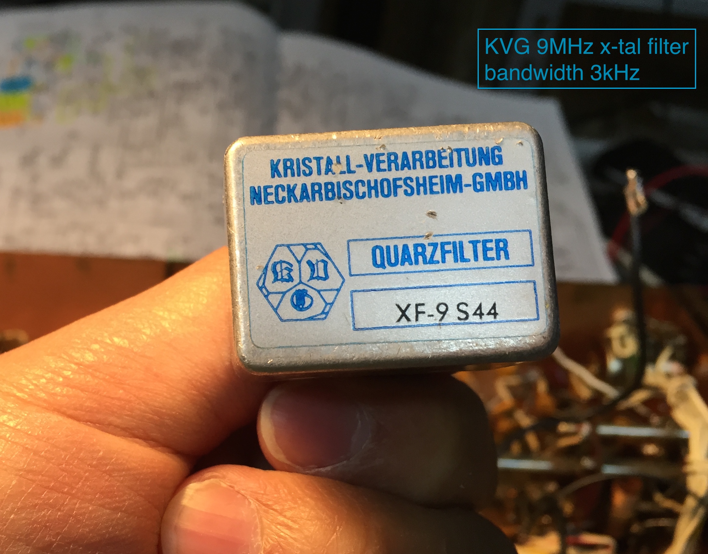
I selected a used KVG 9MHz USB filter for this mod. It's center frequency is about 9001.5kc and the bandwidth is about 3kc. I wrote the code to switch the carrier between about 9000.0kc and 9003.0kc. In the X-CW mode, it becomes 9001.5kc. For real CW work, 600-800Hz shift would be better, but I intended this to be a sideband-only rig.
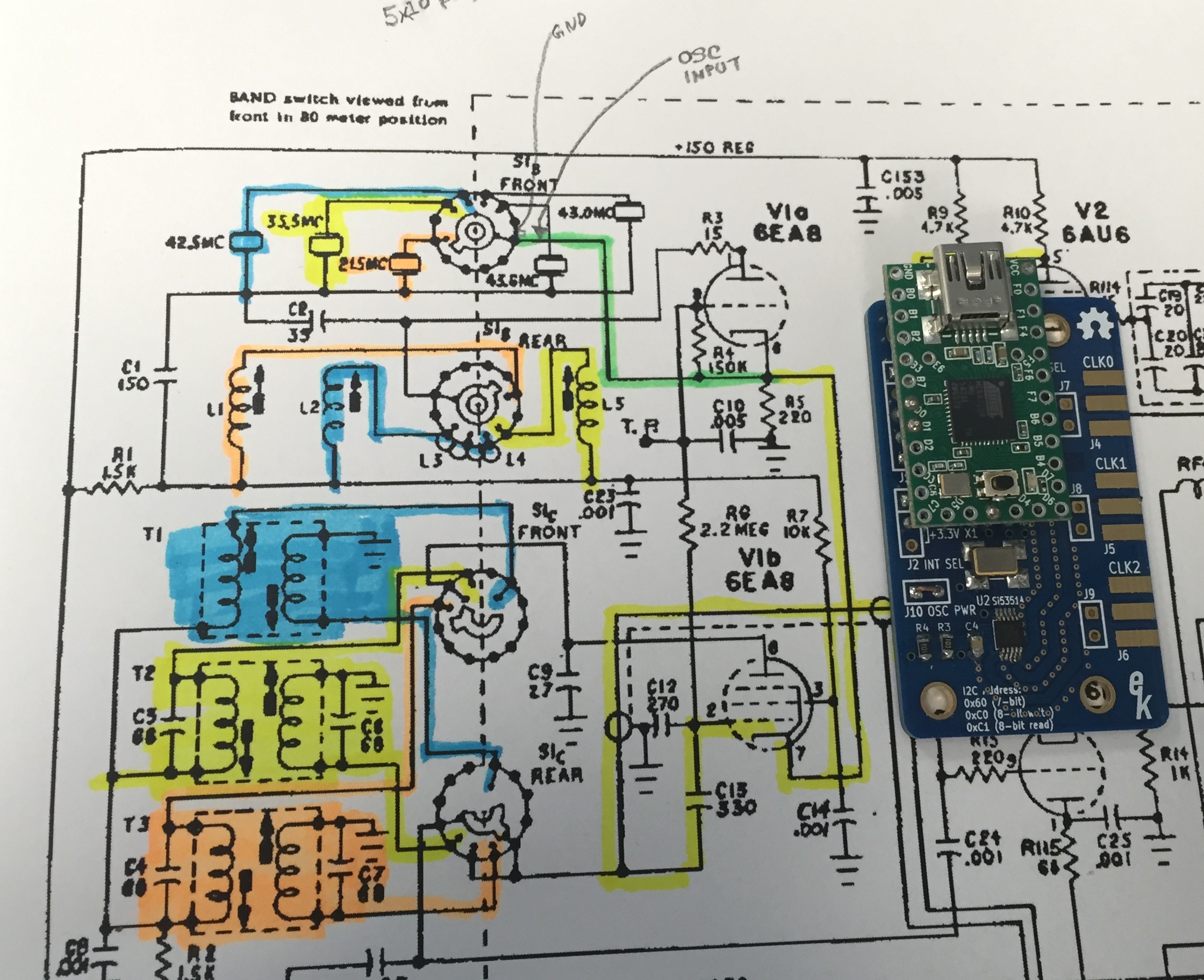
I tested the carrier switching by connecting one of the si5351 output to the grid of 6GX6. If the carrier is the only signal to generate, the mod is very simple. I have an example here. Generating the band LO signal needs a bit more work.
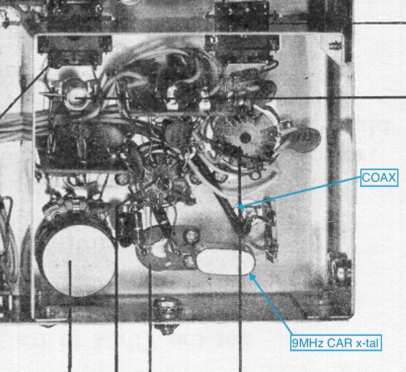
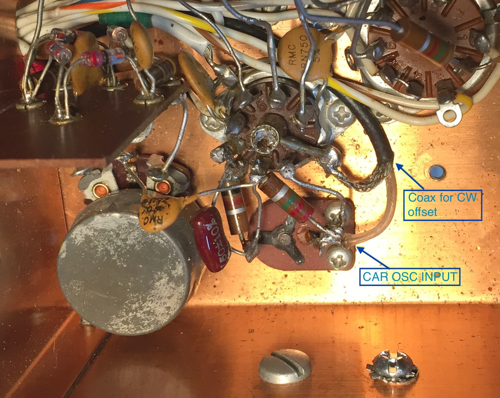
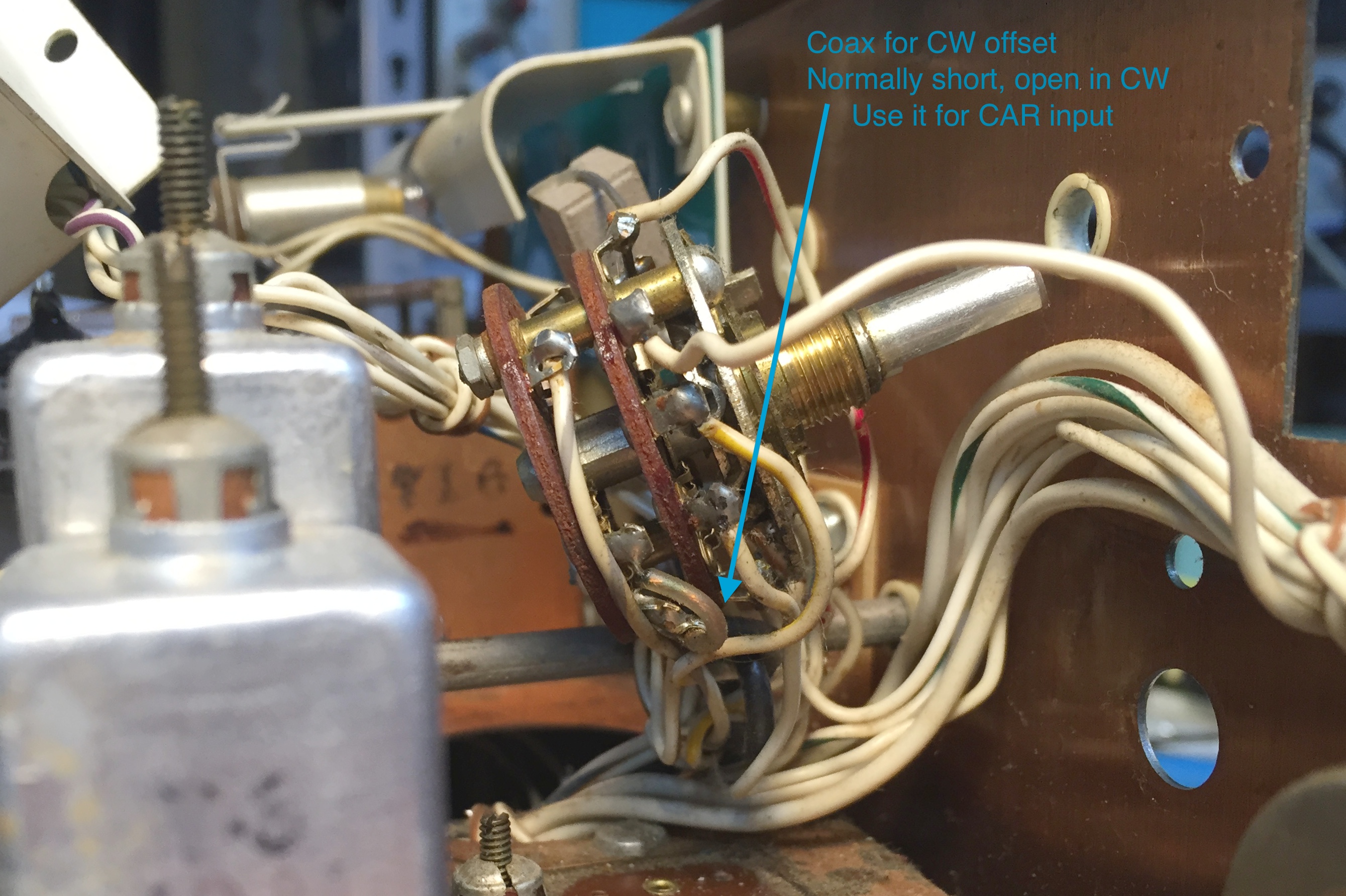
The sideband switching can be easily sensed from the sideband selection rotary switch. All one needs is to ground a pin when one sideband is selected. Sensing X-CW is also easy. The thin coax runs from the front panel to the carrier crystal will do the job. The coax is used as a capacitor for shifting carrier frequency in X-CW. This is normally shorted and becomes open in X-CW, perfect for sensing through a digital I/O pin. This coax was replaced with a capacitor and a relay in TR-4. The relay actuation line can be repurposed for the X-CW sensing.
If the band LO signal is to be also generated, the prefered location of the si5351 may be different and the wiring will be different too. I will describe what I did as best I can.
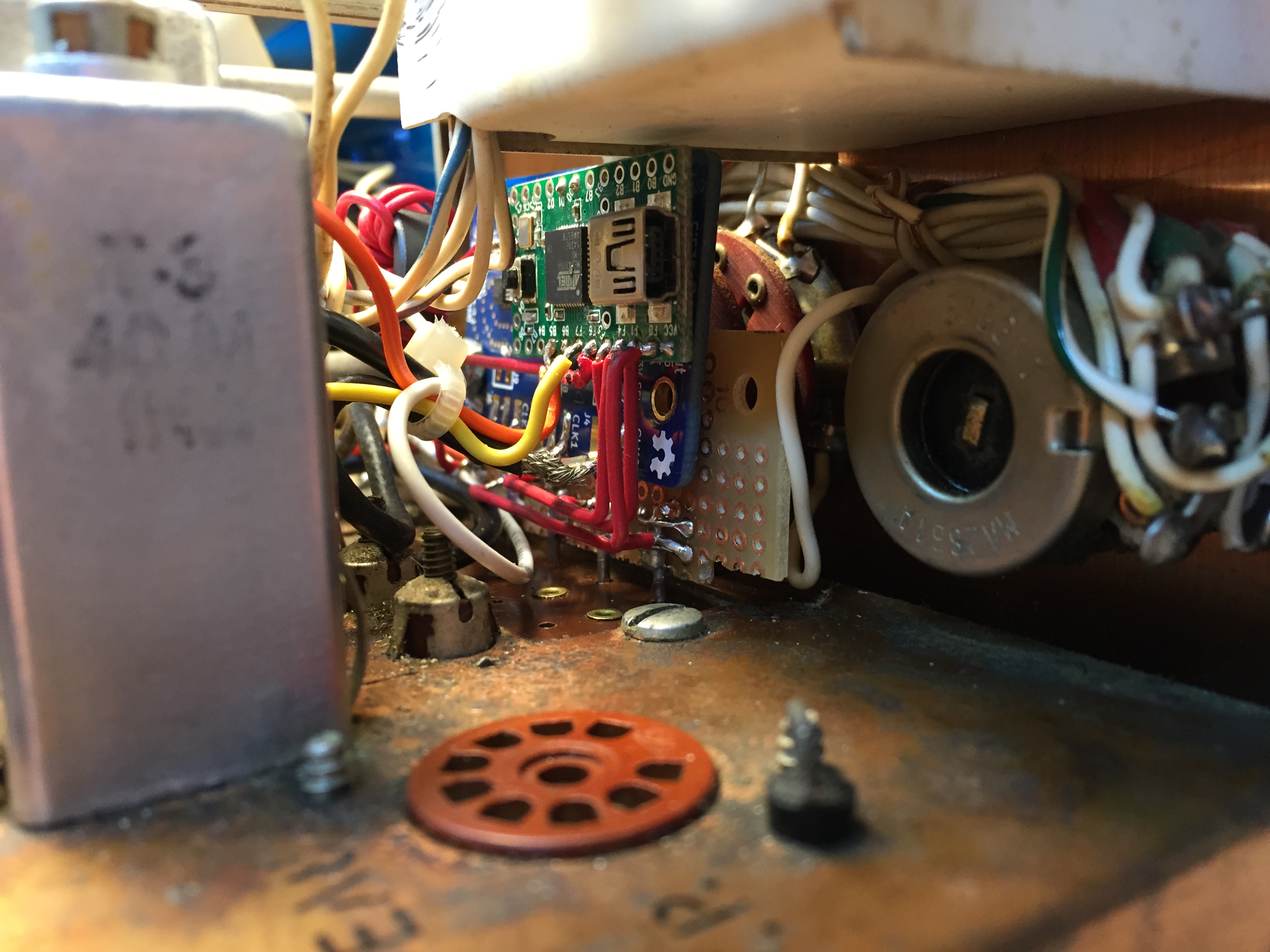
I decided to mount the boards right where the band crystals were. That way I don't have to run five band sensing lines. I first constructed an adapter.
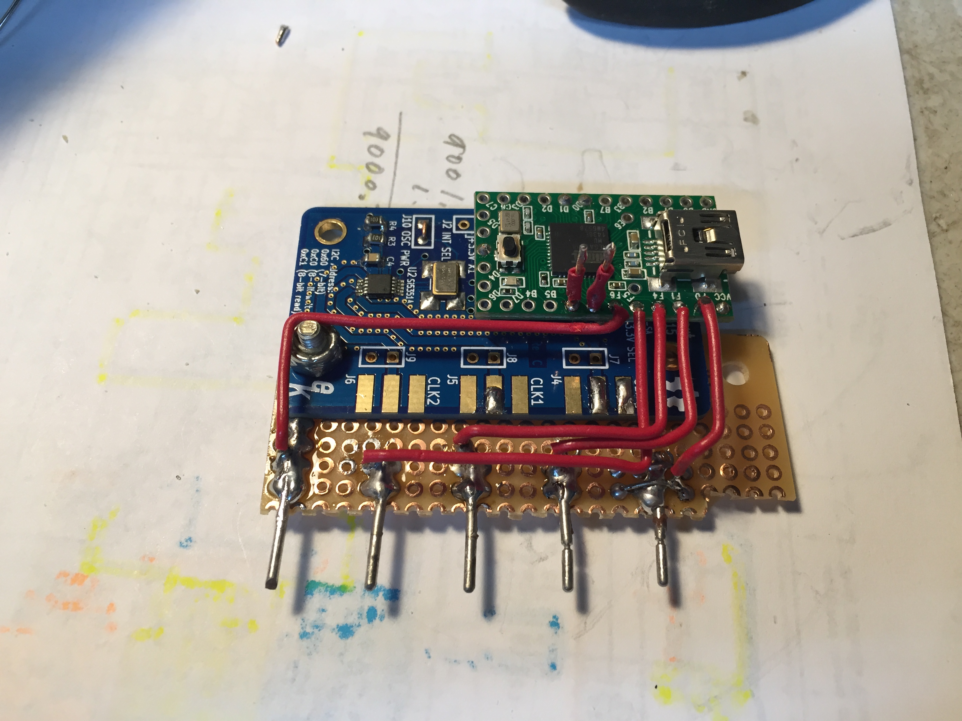
Then mounted the boards and connected the I/O pins. When a band is selected, the corresponding crystal is connected to the cathode of V1a. I simple moved it to ground, so that the band sensing works through the digital I/O pins. The output signal is connected to the cathode. There will be no input for 20m/80m.
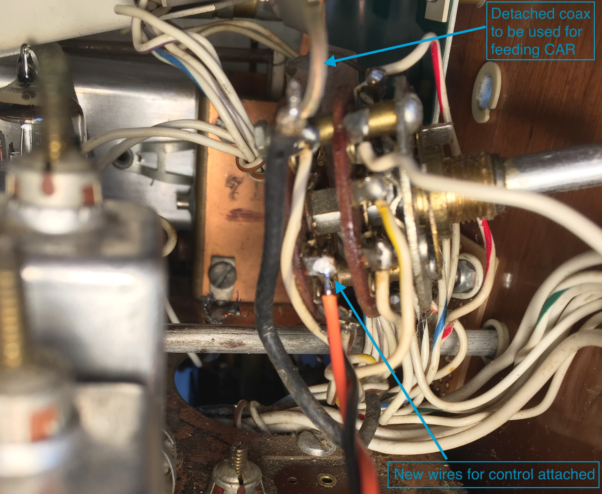
Since the generated carrier needs to be fed to 6GX6 all the way in the back, I decided to use the existing thin coax for it, rather than running a new cable.
That involved removing the front panel and unmounting the mode switch. I unsoldered the coas from the switch and soldered a pair of regular wires in place for the X-CW sensing. This end of the coax was connected to the carrier output of si5351. One of the newly soldered wire was grounded and the other one was connected to an I/O pin.
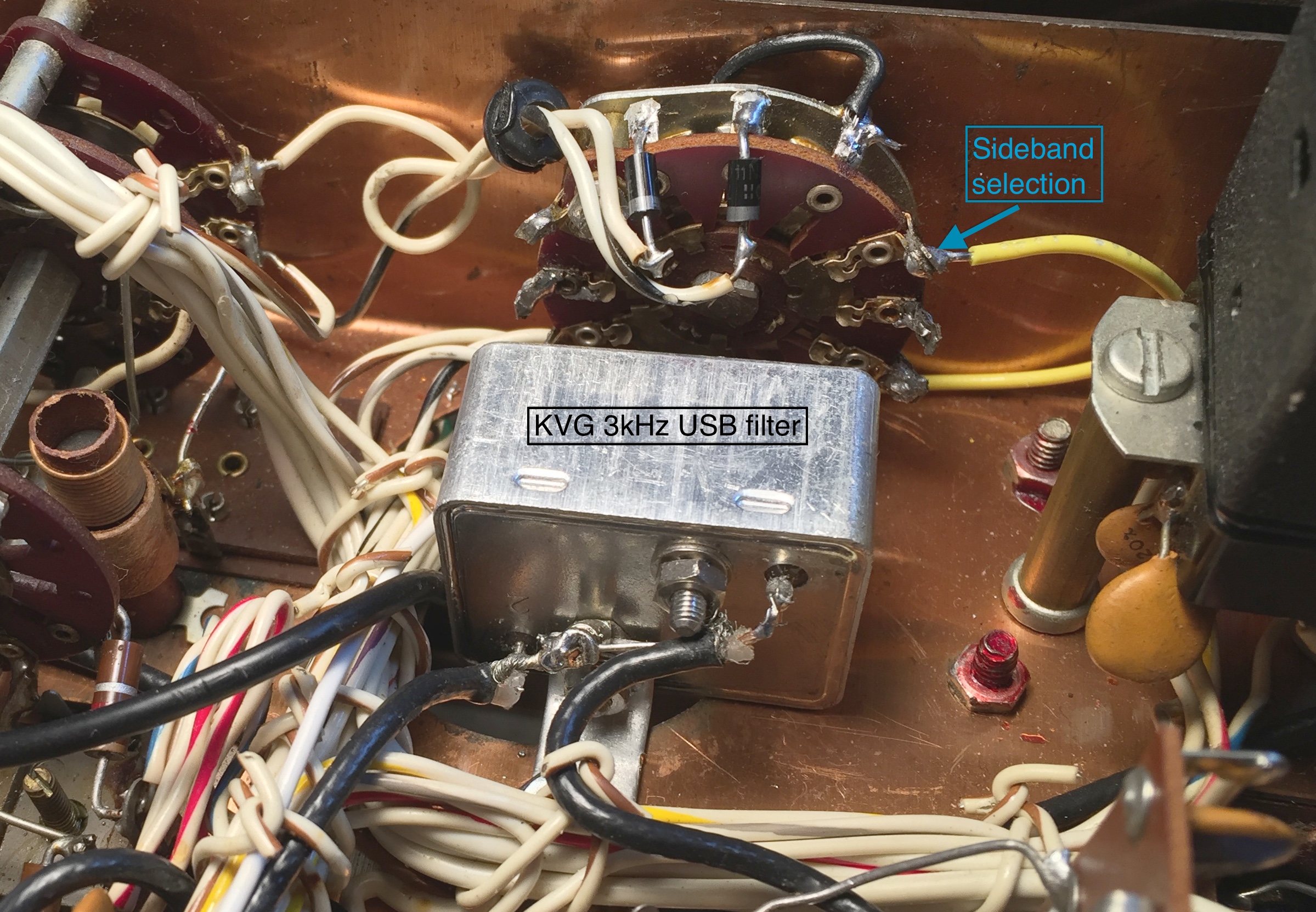
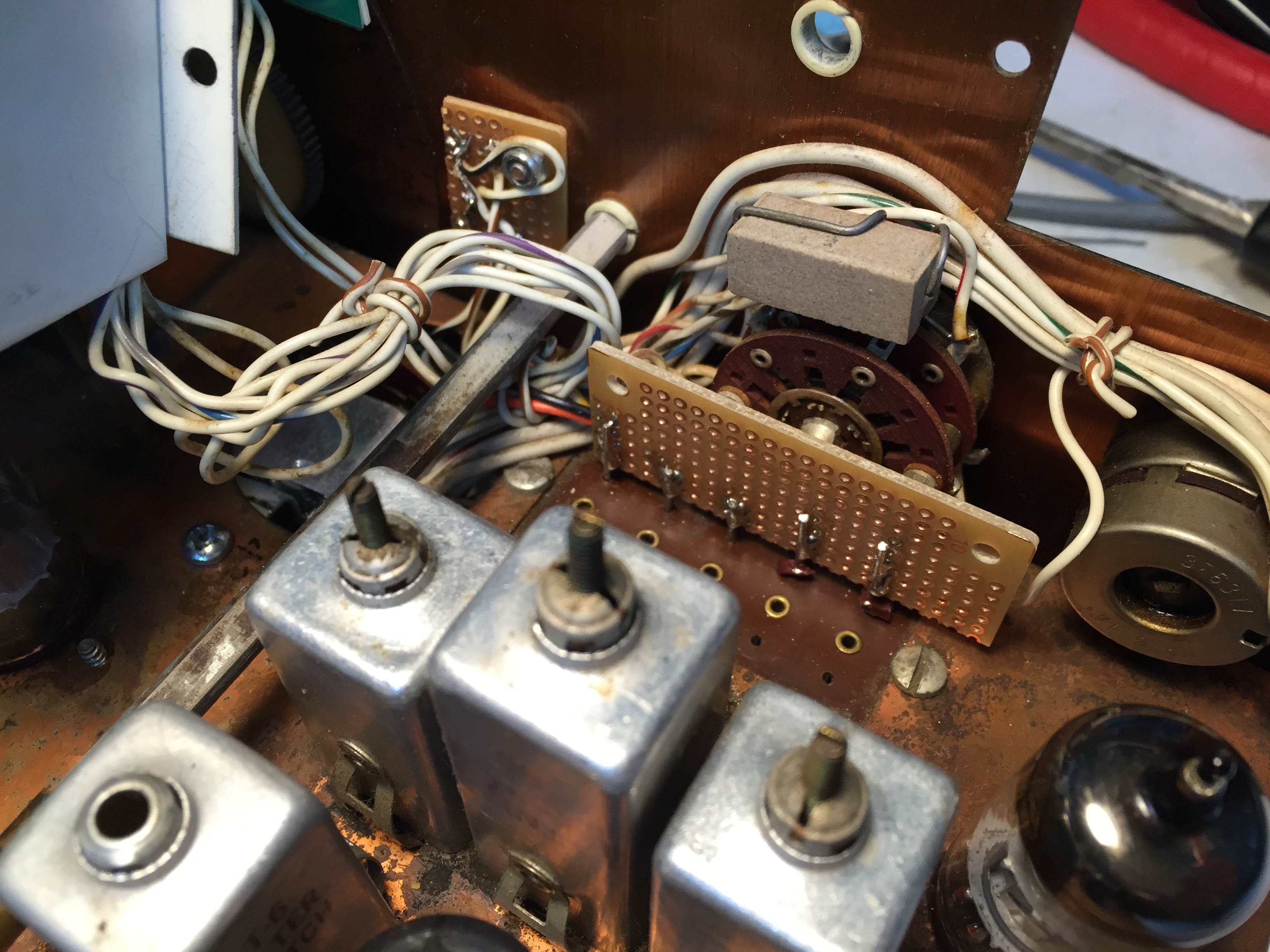
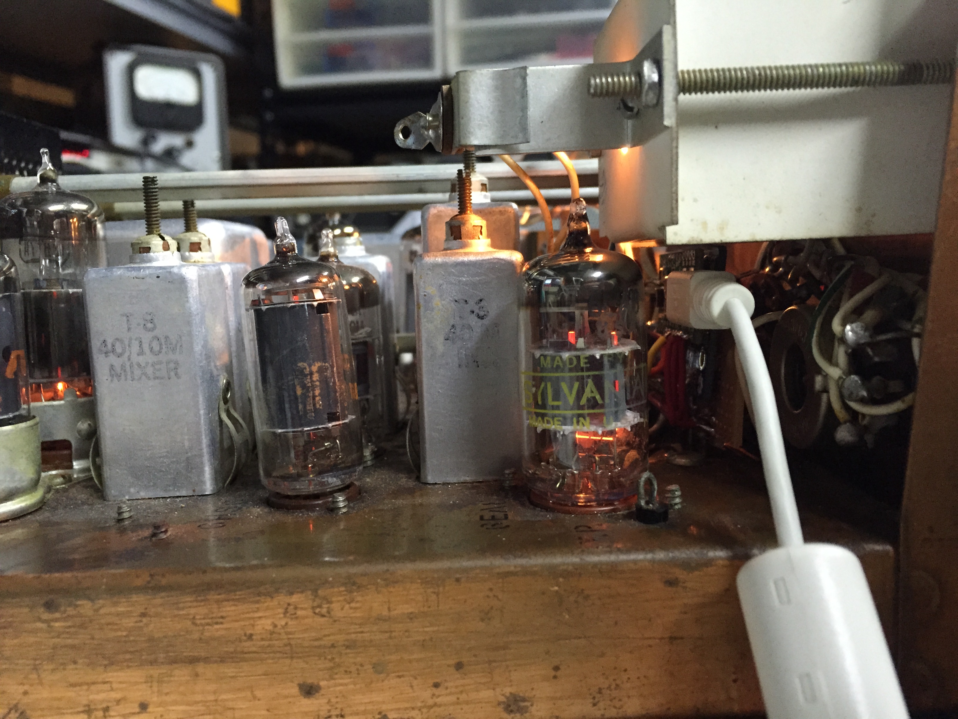
This picture shows the mounted and hard-wired KVG filter and the sideband selector.
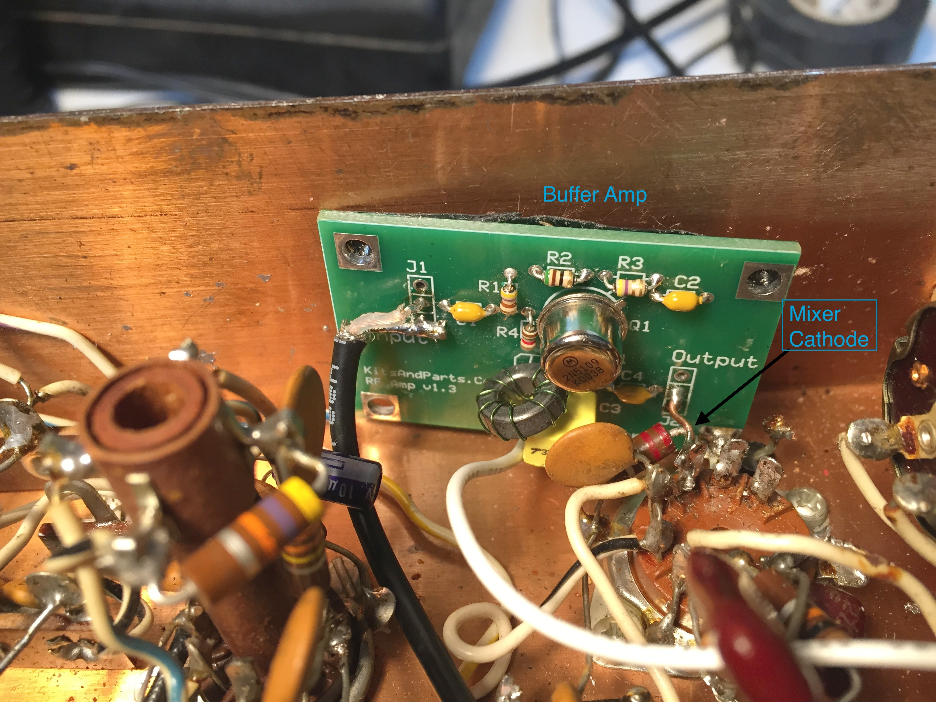
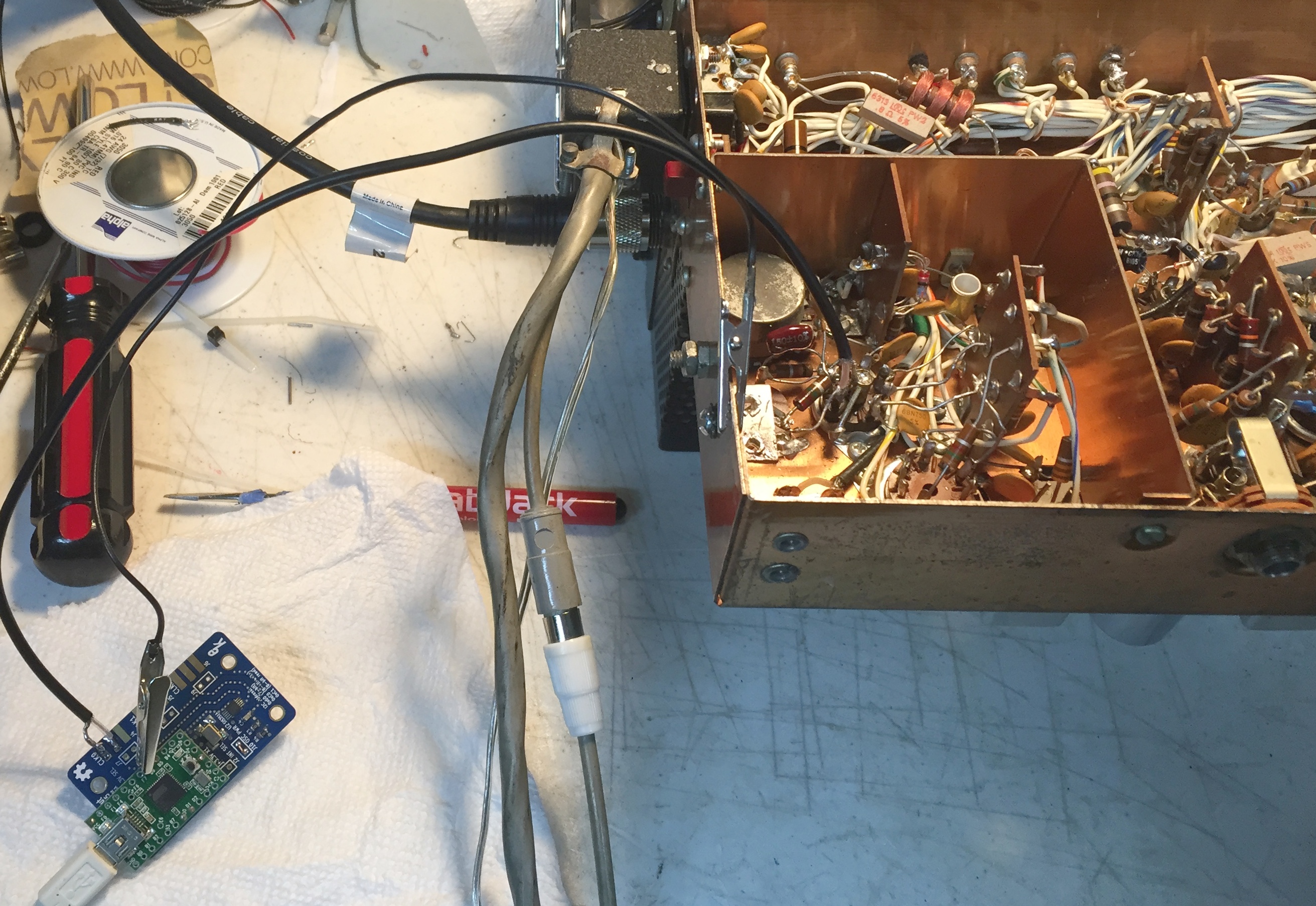
Everything seemed working fine until I tried to transmit. It did transmit, but the power output was only about 30-50%. As an easy solution I ended up installing a buffer amp I already had. There might be a better solution for this. The output impedance of this amp is 200 ohms.
The board has a USB port for reprogramming. For this particular unit, I chose to supply the 5V externally, so it is possible to do in-circuit reprogramming. When developing and testing, I can disconnect the external power source and use USB to power this module. I can observe the effect of reprogramming right away.
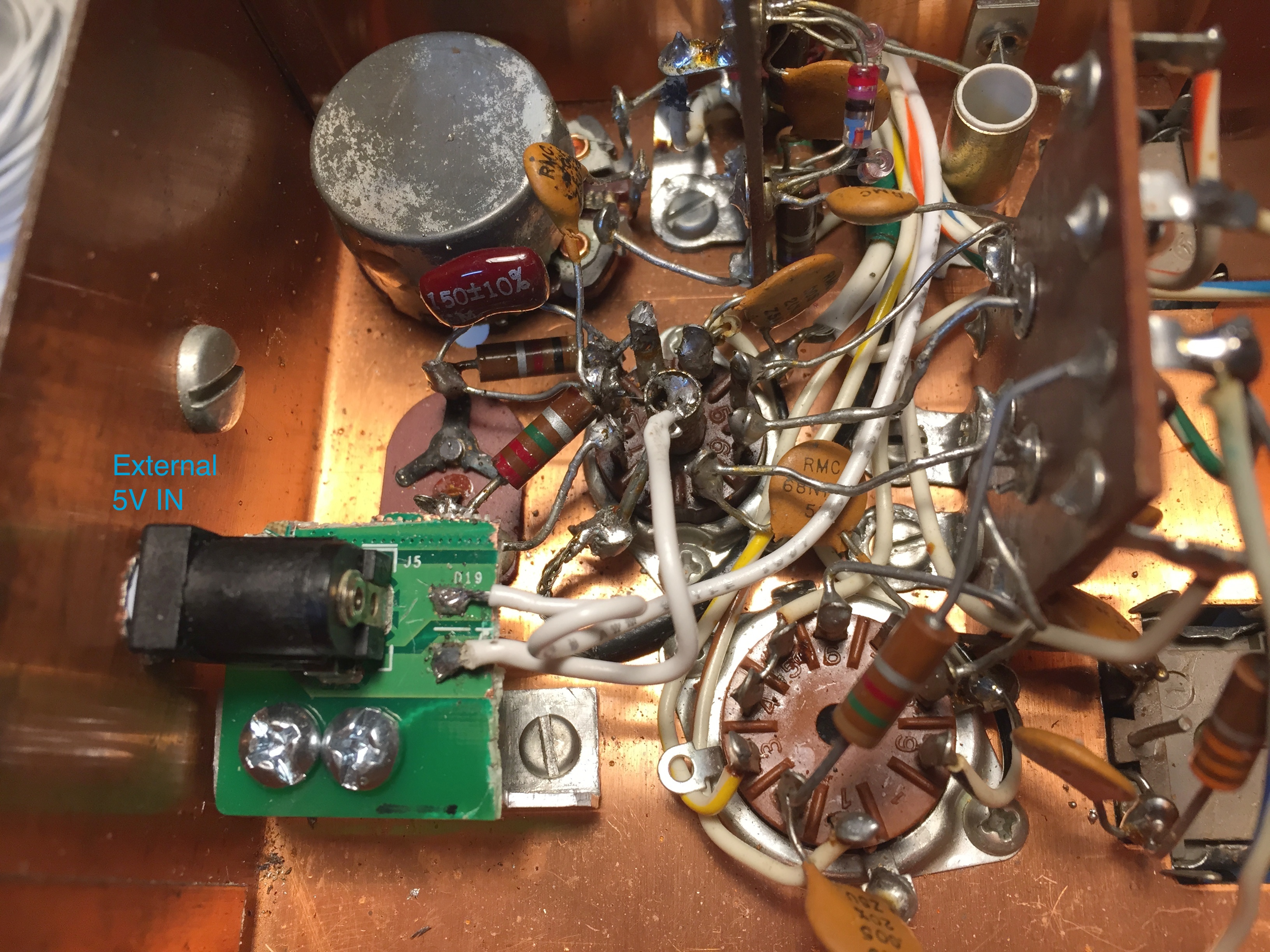
This is where I added the power jack. There already was a hole drilled by a previous owner. I just enlarged it. I am using a 5V linear power wall wart that was originally for an external IOmega ZIP drive.
In-circuit programming in action.
I tried to make the dial calibration least painful. Since I don't operate 75/80m much, I adjusted the band LO, so that they all align from 40m LSB to 10m USB. Only on 80m LSB, it will be off about 3kc.
Links
Teensy USB Development Board. There are plenty others that can be used with Arduino.
si5351 board from Adafruit
Etherkit Si5351A Breakout Board (NT7S)
Arduino si5351 library by NT7S
K9SUL's TR-3/4 signal generator code. May not be up-to-date.
|